- 您现在的位置:买卖IC网 > Sheet目录3826 > PIC18F4455-I/ML (Microchip Technology)IC PIC MCU FLASH 12KX16 44QFN
2009 Microchip Technology Inc.
DS39632E-page 125
PIC18F2455/2550/4455/4550
10.5
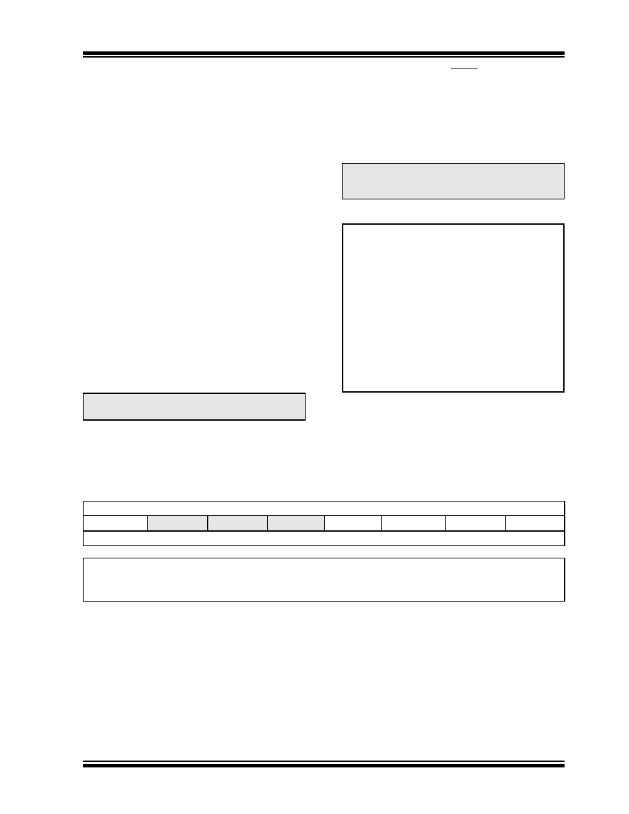
PORTE, TRISE and LATE
Registers
Depending on the particular PIC18F2455/2550/4455/
4550 device selected, PORTE is implemented in two
different ways.
For 40/44-pin devices, PORTE is a 4-bit wide port.
Three pins (RE0/AN5/CK1SPP, RE1/AN6/CK2SPP
and RE2/AN7/OESPP) are individually configurable as
inputs or outputs. These pins have Schmitt Trigger
input buffers. When selected as an analog input, these
pins will read as ‘0’s.
The corresponding Data Direction register is TRISE.
Setting a TRISE bit (= 1) will make the corresponding
PORTE pin an input (i.e., put the corresponding output
driver in a high-impedance mode). Clearing a TRISE bit
(= 0) will make the corresponding PORTE pin an output
(i.e., put the contents of the output latch on the selected
pin).
In addition to port data, the PORTE register
(Register 10-1) also contains the RDPU control bit
(PORTE<7>); this enables or disables the weak
pull-ups on PORTD.
TRISE controls the direction of the RE pins, even when
they are being used as analog inputs. The user must
make sure to keep the pins configured as inputs when
using them as analog inputs.
The Data Latch register (LATE) is also memory
mapped. Read-modify-write operations on the LATE
register read and write the latched output value for
PORTE.
The fourth pin of PORTE (MCLR/VPP/RE3) is an input
only pin. Its operation is controlled by the MCLRE Config-
uration bit. When selected as a port pin (MCLRE = 0), it
functions as a digital input only pin; as such, it does not
have TRIS or LAT bits associated with its operation.
Otherwise, it functions as the device’s Master Clear input.
In either configuration, RE3 also functions as the
programming voltage input during programming.
EXAMPLE 10-5:
INITIALIZING PORTE
10.5.1
PORTE IN 28-PIN DEVICES
For 28-pin devices, PORTE is only available when Mas-
ter Clear functionality is disabled (MCLRE = 0). In these
cases, PORTE is a single bit, input only port comprised
of RE3 only. The pin operates as previously described.
Note:
On a Power-on Reset, RE2:RE0 are
configured as analog inputs.
Note:
On a Power-on Reset, RE3 is enabled as
a digital input only if Master Clear
functionality is disabled.
CLRF
PORTE
; Initialize PORTE by
; clearing output
; data latches
CLRF
LATE
; Alternate method
; to clear output
; data latches
MOVLW
0Ah
; Configure A/D
MOVWF
ADCON1 ; for digital inputs
MOVLW
03h
; Value used to
; initialize data
; direction
MOVLW
07h
; Turn off
MOVWF
CMCON
; comparators
MOVWF
TRISC
; Set RE<0> as inputs
; RE<1> as outputs
; RE<2> as inputs
REGISTER 10-1:
PORTE REGISTER
R/W-0
U-0
R/W-x
R/W-0
RDPU(3)
—
RE3(1,2)
RE2(3)
RE1(3)
RE0(3)
bit 7
bit 0
Legend:
R = Readable bit
W = Writable bit
U = Unimplemented bit, read as ‘0’
-n = Value at POR
‘1’ = Bit is set
‘0’ = Bit is cleared
x = Bit is unknown
bit 7
RDPU: PORTD Pull-up Enable bit
1 = PORTD pull-ups are enabled by individual port latch values
0 = All PORTD pull-ups are disabled
bit 6-4
Unimplemented: Read as ‘0’
bit 3-0
RE3:RE0: PORTE Data Input bits(1,2,3)
Note 1:
implemented only when Master Clear functionality is disabled (MCLRE Configuration bit = 0); otherwise,
read as ‘0’.
2:
RE3 is the only PORTE bit implemented on both 28-pin and 40/44-pin devices. All other bits are
implemented only when PORTE is implemented (i.e., 40/44-pin devices).
3:
Unimplemented in 28-pin devices; read as ‘0’.
发布紧急采购,3分钟左右您将得到回复。
相关PDF资料
PIC24FJ64GB108-I/PT
IC PIC MCU FLASH 80TQFP
DSPIC33FJ64MC506A-I/PT
IC DSPIC MCU/DSP 64K 64-TQFP
PIC16F877A-I/P
IC MCU FLASH 8KX14 EE 40DIP
MP2-HS240-51
CONN SHROUD 2-FB 240POS 5ROW
DSPIC33FJ64MC506-I/PT
IC DSPIC MCU/DSP 64K 64TQFP
DSPIC33FJ128MC802-I/SO
IC DSPIC MCU/DSP 128K 28SOIC
PIC18LF4331-I/P
IC PIC MCU FLASH 4KX16 40DIP
DSPIC33FJ128GP306-I/PT
IC DSPIC MCU/DSP 128K 64TQFP
相关代理商/技术参数
PIC18F4455-I/P
功能描述:8位微控制器 -MCU 24kBF 2048RM FSUSB2 RoHS:否 制造商:Silicon Labs 核心:8051 处理器系列:C8051F39x 数据总线宽度:8 bit 最大时钟频率:50 MHz 程序存储器大小:16 KB 数据 RAM 大小:1 KB 片上 ADC:Yes 工作电源电压:1.8 V to 3.6 V 工作温度范围:- 40 C to + 105 C 封装 / 箱体:QFN-20 安装风格:SMD/SMT
PIC18F4455-I/PT
功能描述:8位微控制器 -MCU 24kBF 2048RM FSUSB2 RoHS:否 制造商:Silicon Labs 核心:8051 处理器系列:C8051F39x 数据总线宽度:8 bit 最大时钟频率:50 MHz 程序存储器大小:16 KB 数据 RAM 大小:1 KB 片上 ADC:Yes 工作电源电压:1.8 V to 3.6 V 工作温度范围:- 40 C to + 105 C 封装 / 箱体:QFN-20 安装风格:SMD/SMT
PIC18F4455T-I/ML
功能描述:8位微控制器 -MCU 24kBF 2048RM FSUSB2 RoHS:否 制造商:Silicon Labs 核心:8051 处理器系列:C8051F39x 数据总线宽度:8 bit 最大时钟频率:50 MHz 程序存储器大小:16 KB 数据 RAM 大小:1 KB 片上 ADC:Yes 工作电源电压:1.8 V to 3.6 V 工作温度范围:- 40 C to + 105 C 封装 / 箱体:QFN-20 安装风格:SMD/SMT
PIC18F4455T-I/PT
功能描述:8位微控制器 -MCU 24kBF 2048RM FSUSB2 RoHS:否 制造商:Silicon Labs 核心:8051 处理器系列:C8051F39x 数据总线宽度:8 bit 最大时钟频率:50 MHz 程序存储器大小:16 KB 数据 RAM 大小:1 KB 片上 ADC:Yes 工作电源电压:1.8 V to 3.6 V 工作温度范围:- 40 C to + 105 C 封装 / 箱体:QFN-20 安装风格:SMD/SMT
PIC18F4458-I/ML
功能描述:8位微控制器 -MCU 24KB Flash 2KB RAM RoHS:否 制造商:Silicon Labs 核心:8051 处理器系列:C8051F39x 数据总线宽度:8 bit 最大时钟频率:50 MHz 程序存储器大小:16 KB 数据 RAM 大小:1 KB 片上 ADC:Yes 工作电源电压:1.8 V to 3.6 V 工作温度范围:- 40 C to + 105 C 封装 / 箱体:QFN-20 安装风格:SMD/SMT
PIC18F4458-I/P
功能描述:8位微控制器 -MCU 24KB Flash 2KB RAM RoHS:否 制造商:Silicon Labs 核心:8051 处理器系列:C8051F39x 数据总线宽度:8 bit 最大时钟频率:50 MHz 程序存储器大小:16 KB 数据 RAM 大小:1 KB 片上 ADC:Yes 工作电源电压:1.8 V to 3.6 V 工作温度范围:- 40 C to + 105 C 封装 / 箱体:QFN-20 安装风格:SMD/SMT
PIC18F4458-I/PT
功能描述:8位微控制器 -MCU 24KB Flash 2KB RAM RoHS:否 制造商:Silicon Labs 核心:8051 处理器系列:C8051F39x 数据总线宽度:8 bit 最大时钟频率:50 MHz 程序存储器大小:16 KB 数据 RAM 大小:1 KB 片上 ADC:Yes 工作电源电压:1.8 V to 3.6 V 工作温度范围:- 40 C to + 105 C 封装 / 箱体:QFN-20 安装风格:SMD/SMT
PIC18F4458T-I/ML
功能描述:8位微控制器 -MCU 24KB Flash 2KB RAM RoHS:否 制造商:Silicon Labs 核心:8051 处理器系列:C8051F39x 数据总线宽度:8 bit 最大时钟频率:50 MHz 程序存储器大小:16 KB 数据 RAM 大小:1 KB 片上 ADC:Yes 工作电源电压:1.8 V to 3.6 V 工作温度范围:- 40 C to + 105 C 封装 / 箱体:QFN-20 安装风格:SMD/SMT